PCB & Electronics
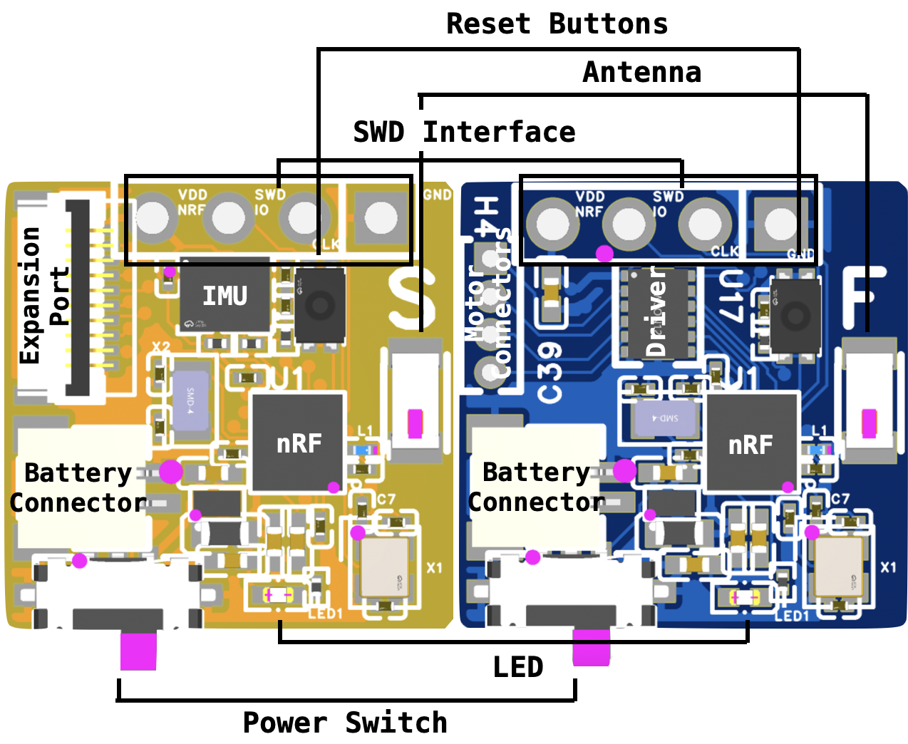
Both sensing and feedback stickies are built around the nRF52832.
The sensing Sticky integrates a 6-axis IMU and an expansion port for optional add-on sensing. The feedback Sticky integrates a motor driver and up to 2 ERM vibrotactile motor. The Vybronics VC0720B015F is used in our evaluation. The motors are the only components that need to be hand-soldered with PCBA orders (see Order PCBA for ordering details).
All schematics and layouts are available at our GitHub Repo, including:
- sensing sticky,
- feedback sticky, and
- optional tactile expansion.
Since the boards were designed using EasyEDA, the easiest way to view the designs are to upload them into EasyEDA pro and export it into EDA other softwares if needed.
Tactile Patch Assembly
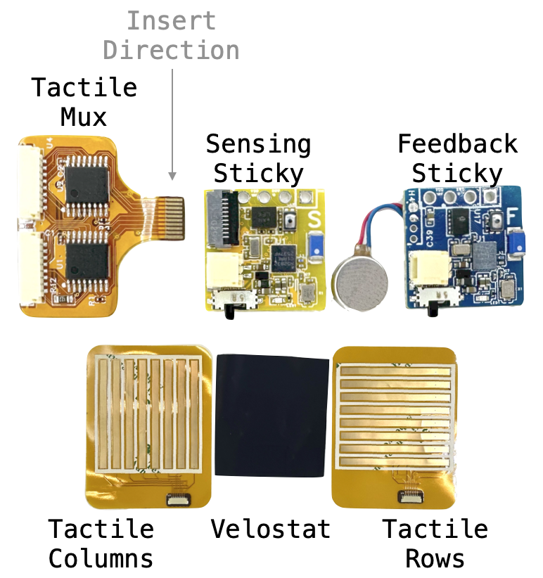
To assemble the optional tactile sensing patch, sandwich a sheet of velostat between the row and column tactile patches. The tactile patches already have adhesive on them: just peel the white protective sheet off.
Tactile Patch Connections
The Tactile Mux board's FPC connector inserts into the Sensing Sticky's expansion port in the direction shown. The tactile columns and tactile rows patches sandwich the Velostat sheet between them, as described above. Two JST 08SUR connector cables are needed: one for each column/row patch. Here are options of different lengths, depending on desired applications: