Firmware Setup & Flashing
Switch on the Sticky.
If you see a blinking blue light, firmware is already flashed — skip ahead to Using the App.
If there's no blink, either the firmware hasn't been flashed yet (continue with this guide) or the battery is dead.
If you have physical Stickies but haven't flashed firmware onto them yet, start here. For each Sticky, the firmware only needs to be flashed once, after PCB assembly, over an SWD interface using a pogo-pin probe clip and a J-Link programmer.
- A J-Link programmer (J-Link BASE Classic from Segger or an SWD Debug Probe compatible with SEGGER J-Link Software )
- A pogo-pin probe clip.
- Male-to-Male DuPont Wires
- Comfort with use command lines — no embedded programming experience required, this guide only uses prebuilt firmware images. Note, the firmware flashing workflow has only been tested on macOS and Linux.
J-Link Setup
- Install the J-Link Software and Documentation Pack.
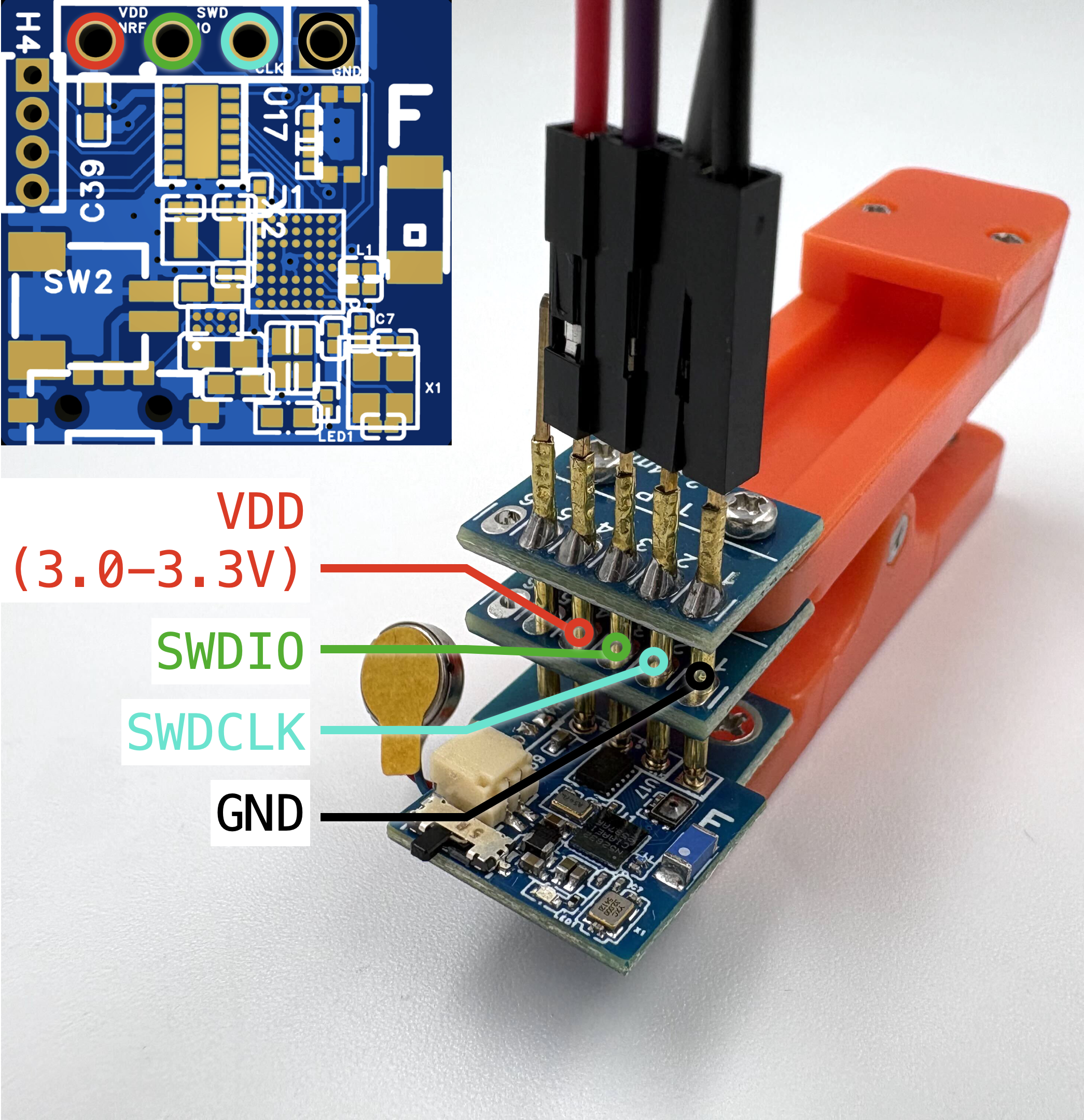
- Connect the pogo-pin probe clip to the J-Link: From left to right as shown in the image (here we show an example with the feedback sticky but the order remains the same for a sensing sticky) below. Use male-to-male DuPont wires to wire
VDD,SWDIO,SWDCLK,GNDto corresponding pins on the J-Link.
Flash the Firmware
- Launch
JLinkExe, from the downloaded J-Link Software and Documentation Pack. - Type
connect. Press the Return key. - Type
NRF52832_XXAAto specify the target device. Press the Return key.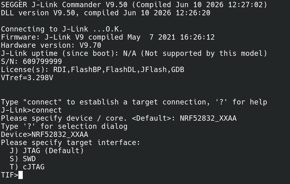
- Type
sto select SWD.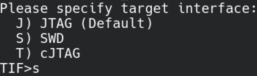
- Choose the default speed by pressing the Return key.

- Type
erasebefore each firmware upload. Press the Return key.
- Wait for
Erasing doneand typeloadfile <filepath.hex>to upload each hex file (use absolute path) separately. Sensing sticky firmware binaries and feedback sticky firmware binaries are available at our GitHub Repo.
- After uploading, type
reset. Press the Return key.
- Wait for resets, then type
go. Press the Return key.
- You should a few blinking blue lights after
go. You can check whether the Sticky is properly advertising over BLE using the nRF Connect mobile app.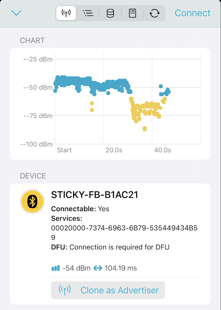
The Sticky is now ready to use! Continue to Using the App to connect them.
Two role-specific firmware images exist: one shared across all sensing stickies, one shared across all feedback stickies. After firmware flashing, each Sticky advertises with the naming convention STICKY-XX-XXXXXX. The middle field identifies the Sticky type: SENSE for a sensing Sticky or FB for a feedback Sticky. The final six characters are taken from the unique chip identifier and distinguish individual devices.